SPI module reference
#include <spi.h>Makefile :
MODULES+=spi
Description
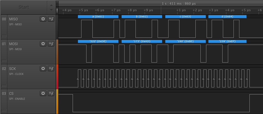
SPI is a widely-used serial communication bus used to interface other components such as external memories or sensors. Take a look at the Communication buses tutorial for more details on how SPI compares to other protocols such as I2C.
The SPI controller can act as either a Master or a Slave.
Master mode
In Master mode, the controller allows to perform arbitrary transfers with up to 4 peripherals. The API is pretty straightforward : set up a new peripheral using the addPeripheral() function, then use one of the two transfer() functions to send and receive data.
Note that since SPI is a full-duplex protocol (meaning that there is one electrical line for sending data and one for receiving data), a transfer necessarily implies that a byte is received while another one is sent. However, in case some data is not meaningful (for exemple, you only want to send some command to a slave, and the data received at the same time is not meaningful, such as null padding bytes), the library provides helpers to avoid having to define useless buffers. See the description of the transfer() functions below, especially the next and partial parameters.
While SPI is pretty much standardised, some peripherals might require unusual settings regarding the phase and polarity of the signals, called the SPI mode. Wikipedia gives a great overview of this in the Clock polarity and phase chapter of the SPI article. Each slave can have a dedicated mode, making easy to have peripherals using different modes on the same bus. However, most peripheral are compatible with the default MODE0 value and this setting rarely needs to be changed.
Here is a example of a simple SPI master transfer with a Carbide :
#include <carbide.h>
#include <core.h>
#include <spi.h>

// The CS pin of the peripheral is connected to the NPCS0 line
const SPI::Peripheral peripheral = 0;

int main() {
    // Initialize the board
    Carbide::init();

    // Enable the SPI controller in Master mode and register a peripheral on NPCS0
    SPI::enableMaster();
    SPI::addPeripheral(peripheral);

    // Tx buffer containing some data to send
    uint8_t txBuffer[4] = {0xDE, 0xAD, 0xBE, 0xEF};

    // Rx buffer where the received data will be stored
    uint8_t rxBuffer[4];

    while (true) {
        // Perform a transfer with the peripheral
        SPI::transfer(peripheral, txBuffer, sizeof(txBuffer), rxBuffer, sizeof(txBuffer));

        // Blink the blue LED and wait for 1 sec
        Carbide::setLedB();
        Core::sleep(100);
        Carbide::setLedB(false);
        Core::sleep(900);
    }
}
Slave mode
In Slave mode, since the controller has no control over when the transfers happen (this is the master's role), all transfers are asynchronous. A transfer is set up using slaveTransfer() with a buffer containing the data to send during the next transfer initiated by the master. If the master requests more bytes than the buffer contains, null bytes will be automatically sent as necessary.
The end of the transfer is checked either by polling (using isSlaveTransferFinished()) or by interrupt (by registering a handler with enableSlaveTransferFinishedInterrupt()).
When the transfer is finished, the received data (which was sent by the master) can be read using slaveGetReceivedData() and a new transfer can be set up by calling slaveTransfer() again.
Check the code below for an example of an SPI slave implementation as well as a comparison between polling and interrupt :
Polling :
#include <carbide.h>
#include <core.h>
#include <spi.h>

int main() {
    // Initialize the board
    Carbide::init();

    // Enable the SPI controller in Slave mode
    SPI::enableSlave();

    // Tx buffer containing some data to send
    uint8_t txBuffer[] = {'a', 'b', 'c', 'd', 'e', 'f', 'g'};

    // Rx buffer where the received data will be stored
    uint8_t rxBuffer[10];

    // Set up a transfer
    SPI::slaveTransfer(txBuffer, sizeof(txBuffer));

    while (true) {
        // Check if the transfer is finished
        if (SPI::isSlaveTransferFinished()) {
            // Get the received data into the rx buffer
            int rxSize = SPI::slaveGetReceivedData(rxBuffer, sizeof(rxBuffer));

            // Set up the next transfer
            SPI::slaveTransfer(txBuffer, sizeof(txBuffer));

            // Blink the blue LED to indicate a transfer has been performed,
            // as well as the green LED if it matches a known value
            Carbide::setLedB();
            if (rxSize == 4 && rxBuffer[0] == 0xDE && rxBuffer[1] == 0xAD
                    && rxBuffer[2] == 0xBE && rxBuffer[3] == 0xEF) {
                Carbide::setLedG();
            }
            Core::sleep(100);
            Carbide::setLedB(false);
            Carbide::setLedG(false);
        }
    }
}
Interrupt :
#include <carbide.h>
#include <core.h>
#include <spi.h>

// Flags to pass information between the handler and the main loop
volatile bool _transferFinished = false;
volatile int _nReceivedBytes = 0;

// Tx buffer containing some data to send
uint8_t txBuffer[] = {'a', 'b', 'c', 'd', 'e', 'f', 'g'};

// Rx buffer where the received data will be stored
uint8_t rxBuffer[10];

// Handler that will be called whenever a transfer is finished
void spiHandler(int nReceivedBytes) {
    // Get the received data into the rx buffer
    SPI::slaveGetReceivedData(rxBuffer, sizeof(rxBuffer));

    // Set up the next transfer
    SPI::slaveTransfer(txBuffer, sizeof(rxBuffer));

    // Set the flag to tell the main loop that some data has been received
    _transferFinished = true;
    _nReceivedBytes = nReceivedBytes;
}

int main() {
    // Initialize the board
    Carbide::init();

    // Enable the SPI controller in Slave mode
    SPI::enableSlave();

    // Register the interrupt handler
    SPI::enableSlaveTransferFinishedInterrupt(spiHandler);

    // Set up a transfer
    SPI::slaveTransfer(txBuffer, sizeof(txBuffer));

    while (true) {
        // Check if the transfer is finished
        if (_transferFinished) {
            // Blink the blue LED to indicate a transfer has been performed,
            // as well as the green LED if it matches a known value
            Carbide::setLedB();
            if (_nReceivedBytes == 4 && rxBuffer[0] == 0xDE && rxBuffer[1] == 0xAD
                    && rxBuffer[2] == 0xBE && rxBuffer[3] == 0xEF) {
                Carbide::setLedG();
            }
            Core::sleep(100);
            Carbide::setLedB(false);
            Carbide::setLedG(false);

            // Reset the flag
            _transferFinished = false;
            _nReceivedBytes = 0;
        }
    }
}
API
Master mode
addPeripheral() if necessary so this function does not need to be called manually.Peripheral is the number of the peripheral, from zero to SPI::N_PERIPHERALS_MAX = 4, and corresponds to the number of the CS line connected to this peripheral. mode is either MODE0, MODE1, MODE2 or MODE3 (see the module description above for more details on SPI modes).Perform a 1-byte transfer on the bus with the given peripheral. tx is the byte to send and the received byte is returned.
By default, this function will send and receive at the same time (because SPI is full-duplex, see the description above). However, a common use case is to send a command or register byte to a peripheral and receive the response on the next byte : for this purpose, next can be set to true. In this case, the function will send the tx byte, discard the received value, then send a null byte and return the value received then (making it actually a 2-byte transfer).
Perform an arbitrary-length transfer on the bus with the given peripheral by sending data from txBuffer (up to txBufferSize bytes) and storing received data into rxBuffer (up to rxBufferSize).
If rxBufferSize is lower than txBufferSize, only the first received bytes are stored and the last bytes are discarded. Otherwise, if rxBufferSize is greater than txBufferSize, the function will automatically send as much null bytes as necessary after the end of txBuffer to receive the requested number of bytes.
Both txBuffer and rxBuffer can be set to nullptr if necessary (although not at the same time obviously). In this case, the corresponding size should be set to -1. This indicates that the corresponding side of the transfer is not important and will ask the function to, either, send null bytes or discard received bytes, respectively.
Multiple calls to this function can be chained in order to make the the management of buffers easier. In this case, set partial to true on every function call except the last one, in order to prevent the CS line to be deasserted between calls and make it look like a single transfer from the slave's perspective. A common use case is to perform an SPI transfer with two successive calls to transfer : the first one with rxBuffer=nullptr and partial=true to send an multi-byte command to a peripheral, and the second one with txBuffer=nullptr and partial=false to receive the multi-byte response. See the examples for more information.
Slave mode
txBufferSize, null padding bytes will be sent as necessary. A receive-only transfer can be set up by not giving a buffer, in which case only padding bytes will be sent and the received data is read normally using the functions below.slaveTransfer() has been performed yet. In this case, it is usually necessary to call slaveTransfer() again to set up the next transfer.rxBuffer, up to rxBufferSize bytes. The number of bytes received is returned and should be used to correctly parse the buffer.Common functions
Set the GPIO pin used for this port. PinFunction can be MOSI, MISO, SCK, CS0, CS1, CS2 or CS3.
Hacking
Most of the feature set of the hardware peripheral is covered by the driver, although some settings can be tweaked if needed.
The controller has support for more than 4 slaves by using external multiplexing of the four CS lines, in order to support up to 15 peripherals. See the datasheet chapter 26.7.3.6 Peripheral Chip Select Decoding for more information.
In Slave mode, asynchronous data is stored in internal buffers in order to simplify the handling from the user's perspective. The size of these buffers effectively limits the amount of data that can be sent or received in a single transfer, currently to 128 bytes. This can be changed using the SLAVE_BUFFERS_SIZE constant in the driver. Note that it can also be reduced in case only short transfers are necessary and RAM space needs to be saved for other purposes.
Code
Header
#ifndef _SPI_H_
#define _SPI_H_

#include <stdint.h>
#include "gpio.h"
#include "error.h"

// Serial Peripheral Interface
// This module allows the chip to communicate through an SPI interface,
// either as a Master or a Slave.
// SPI is faster than I2C, but uses more wires and can connect to less
// peripherals at the same time.
namespace SPI {

    // Peripheral memory space base addresses
    const uint32_t SPI_BASE = 0x40008000;

    // Register offsets
    const uint32_t OFFSET_CR =   0x00; // Control Register
    const uint32_t OFFSET_MR =   0x04; // Mode Register
    const uint32_t OFFSET_RDR =  0x08; // Receive Data Register
    const uint32_t OFFSET_TDR =  0x0C; // Transmit Data Register
    const uint32_t OFFSET_SR =   0x10; // Status Register
    const uint32_t OFFSET_IER =  0x14; // Interrupt Enable Register
    const uint32_t OFFSET_IDR =  0x18; // Interrupt Disable Register
    const uint32_t OFFSET_IMR =  0x1C; // Interrupt Mask Register
    const uint32_t OFFSET_CSR0 = 0x30; // Chip Select Register 0
    const uint32_t OFFSET_CSR1 = 0x34; // Chip Select Register 1
    const uint32_t OFFSET_CSR2 = 0x38; // Chip Select Register 2
    const uint32_t OFFSET_CSR3 = 0x3C; // Chip Select Register 3
    const uint32_t OFFSET_WPCR = 0xE4; // Write Protection Control Register
    const uint32_t OFFSET_WPSR = 0xE8; // Write Protection Status Register

    // Subregisters
    const uint8_t CR_SPIEN = 0;
    const uint8_t CR_SPIDIS = 1;
    const uint8_t CR_SWRST = 7;
    const uint8_t CR_FLUSHFIFO = 8;
    const uint8_t CR_LASTXFER = 24;
    const uint8_t MR_MSTR = 0;
    const uint8_t MR_PS = 1;
    const uint8_t MR_PCSDEC = 2;
    const uint8_t MR_MODFDIS = 4;
    const uint8_t MR_RXFIFOEN = 6;
    const uint8_t MR_LLB = 7;
    const uint8_t MR_PCS = 16;
    const uint8_t MR_DLYBCS = 24;
    const uint8_t TDR_TD = 0;
    const uint8_t TDR_PCS = 16;
    const uint8_t TDR_LASTXFER = 24;
    const uint8_t SR_RDRF = 0;
    const uint8_t SR_TDRE = 1;
    const uint8_t SR_MODF = 2;
    const uint8_t SR_OVRES = 3;
    const uint8_t SR_NSSR = 8;
    const uint8_t SR_TXEMPTY = 9;
    const uint8_t SR_UNDES = 10;
    const uint8_t SR_SPIENS = 16;
    const uint8_t CSR_CPOL = 0;
    const uint8_t CSR_NCPHA = 1;
    const uint8_t CSR_CSNAAT = 2;
    const uint8_t CSR_CSAAT = 3;
    const uint8_t CSR_BITS = 4;
    const uint8_t CSR_SCBR = 8;
    const uint8_t CSR_DLYBS = 16;
    const uint8_t CSR_DLYBCT = 24;
    const uint8_t WPCR_SPIWPEN = 0;

    // Constants
    const uint32_t WPCR_KEY = 0x535049 << 8;

    const int N_PERIPHERALS_MAX = 4;

    // Error codes
    const Error::Code ERR_INVALID_PERIPHERAL = 0x0001;
    const Error::Code ERR_PERIPHERAL_ALREADY_ENABLED = 0x0002;
    const Error::Code ERR_NOT_MASTER_MODE = 0x0003;
    const Error::Code ERR_NOT_SLAVE_MODE = 0x0004;

    // Static values
    enum class Mode {
        MODE0 = 0, // CPOL=0, CPHA=0
        MODE1 = 1, // CPOL=0, CPHA=1
        MODE2 = 2, // CPOL=1, CPHA=0
        MODE3 = 3  // CPOL=1, CPHA=1
    };

    using Peripheral = uint8_t;

    enum class PinFunction {
        MOSI,
        MISO,
        SCK,
        CS0,
        CS1,
        CS2,
        CS3
    };

    // Master-mode functions
    void enableMaster();
    bool addPeripheral(Peripheral peripheral, Mode mode=Mode::MODE0, int delayBetweenBytes=0);
    uint8_t transfer(Peripheral peripheral, uint8_t tx=0, bool next=false);
    void transfer(Peripheral peripheral, const uint8_t* txBuffer, int txBufferSize, uint8_t* rxBuffer=nullptr, int rxBufferSize=-1, bool partial=false);

    // Slave-mode functions
    void enableSlave(Mode mode=Mode::MODE0);
    void slaveTransfer(const uint8_t* txBuffer=nullptr, int txBufferSize=-1);
    bool isSlaveTransferFinished();
    int slaveGetReceivedData(uint8_t* rxBuffer, int rxBufferSize);
    void enableSlaveTransferFinishedInterrupt(void (*handler)(int nReceivedBytes));
    void disableSlaveTransferFinishedInterrupt();

    // Common functions
    void disable();
    void setPin(PinFunction function, GPIO::Pin pin);

}


#endif
Module
#include "spi.h"
#include "pm.h"
#include "dma.h"
#include "gpio.h"
#include "core.h"
#include "error.h"
#include <string.h>

namespace SPI {

    // Package-dependant, defined in pins_sam4l_XX.cpp
    extern struct GPIO::Pin PIN_MOSI;
    extern struct GPIO::Pin PIN_MISO;
    extern struct GPIO::Pin PIN_SCK;
    extern struct GPIO::Pin PIN_NPCS0;
    extern struct GPIO::Pin PIN_NPCS1;
    extern struct GPIO::Pin PIN_NPCS2;
    extern struct GPIO::Pin PIN_NPCS3;

    bool _enabled = false;
    bool _modeMaster = false;
    int _rxDMAChannel = -1;
    int _txDMAChannel = -1;
    bool _enabledPeripherals[N_PERIPHERALS_MAX] = {false, false, false, false};

    // Used for the DMA channel
    const int DUMMY_BYTES_SIZE = 64;
    uint8_t DUMMY_BYTES[DUMMY_BYTES_SIZE];
    int _dummyBytesCounter = 0;

    // Slave mode
    const int SLAVE_BUFFERS_SIZE = 128;
    uint8_t _slaveTXBuffer[SLAVE_BUFFERS_SIZE];
    uint8_t _slaveRXBuffer[SLAVE_BUFFERS_SIZE];
    int _slaveTransferSize = 0;
    bool _slaveTransferFinished = false;
    void (*_slaveTransferFinishedHandler)(int nReceivedBytes) = nullptr;
    extern uint8_t INTERRUPT_PRIORITY;


    // Internal functions
    void txDMAReloadEmptyHandler();
    void interruptHandlerWrapper();


    void disable() {
        _enabled = false;

        // Free the pins
        GPIO::disablePeripheral(PIN_MISO);
        GPIO::disablePeripheral(PIN_MOSI);
        GPIO::disablePeripheral(PIN_SCK);
        if (_enabledPeripherals[0]) {
            GPIO::disablePeripheral(PIN_NPCS0);
            _enabledPeripherals[0] = false;
        }
        if (_enabledPeripherals[1]) {
            GPIO::disablePeripheral(PIN_NPCS1);
            _enabledPeripherals[1] = false;
        }
        if (_enabledPeripherals[2]) {
            GPIO::disablePeripheral(PIN_NPCS2);
            _enabledPeripherals[2] = false;
        }
        if (_enabledPeripherals[3]) {
            GPIO::disablePeripheral(PIN_NPCS3);
            _enabledPeripherals[3] = false;
        }

        // MR (Mode Register) : deconfigure the interface
        (*(volatile uint32_t*)(SPI_BASE + OFFSET_MR)) = 0;

        // CR (Control Register) : reset the interface
        (*(volatile uint32_t*)(SPI_BASE + OFFSET_CR))
            = 1 << CR_SWRST;        // SWRST : software reset

        // CR (Control Register) : disable the interface
        (*(volatile uint32_t*)(SPI_BASE + OFFSET_CR))
            = 1 << CR_SPIDIS;       // SPIDIS : SPI Disable

        // Disable the clock
        PM::disablePeripheralClock(PM::CLK_SPI);
    }

    void setPin(PinFunction function, GPIO::Pin pin) {
        switch (function) {
            case PinFunction::MOSI:
                PIN_MOSI = pin;
                break;

            case PinFunction::MISO:
                PIN_MISO = pin;
                break;

            case PinFunction::SCK:
                PIN_SCK = pin;
                break;

            case PinFunction::CS0:
                PIN_NPCS0 = pin;
                break;

            case PinFunction::CS1:
                PIN_NPCS1 = pin;
                break;

            case PinFunction::CS2:
                PIN_NPCS2 = pin;
                break;

            case PinFunction::CS3:
                PIN_NPCS3 = pin;
                break;
        }
    }


    void enableMaster() {
        // If the controller is already enabled, disable it first
        if (_enabled) {
            disable();
        }
        _enabled = true;
        _modeMaster = true;

        // Initialize the dummy bytes buffer to 0
        memset(DUMMY_BYTES, 0, sizeof(DUMMY_BYTES));

        // Set the pins in peripheral mode
        GPIO::enablePeripheral(PIN_MISO);
        GPIO::enablePeripheral(PIN_MOSI);
        GPIO::enablePeripheral(PIN_SCK);

        // Enable the clock
        PM::enablePeripheralClock(PM::CLK_SPI);

        // CR (Control Register) : reset the interface
        (*(volatile uint32_t*)(SPI_BASE + OFFSET_CR))
            = 1 << CR_SWRST;        // SWRST : software reset

        // MR (Mode Register) : configure the interface in master mode
        (*(volatile uint32_t*)(SPI_BASE + OFFSET_MR))
            = 1 << MR_MSTR          // MSTR : master mode
            | 0 << MR_PS            // PS : fixed peripheral select
            | 0 << MR_PCSDEC        // PCSDEC : no CS decoding
            | 1 << MR_MODFDIS       // MODFDIS : mode fault detection disabled
            | 1 << MR_RXFIFOEN      // RXFIFOEN : reception fifo enabled
            | 0 << MR_LLB           // LLB : local loopback disabled
            | 0 << MR_PCS           // PCS : will be programmed for each transfer
            | 6 << MR_DLYBCS;       // DLYBCS : delay between chip selects : 6 periods of CLK_SPI

        // CR (Control Register) : enable the interface
        (*(volatile uint32_t*)(SPI_BASE + OFFSET_CR))
            = 1 << CR_SPIEN;        // SPIEN : SPI Enable

        // Set up the DMA channels and related interrupts
        _rxDMAChannel = DMA::setupChannel(_rxDMAChannel, DMA::Device::SPI_RX, DMA::Size::BYTE);
        _txDMAChannel = DMA::setupChannel(_txDMAChannel, DMA::Device::SPI_TX, DMA::Size::BYTE);
    }

    bool addPeripheral(Peripheral peripheral, Mode mode, int delayBetweenBytes) {
        // Make sure the controller is enabled in master mode
        if (!_enabled) {
            enableMaster();
        }
        if (!_modeMaster) {
            Error::happened(Error::Module::SPI, ERR_NOT_MASTER_MODE, Error::Severity::CRITICAL);
            return false;
        }

        if (peripheral >= N_PERIPHERALS_MAX) {
            Error::happened(Error::Module::SPI, ERR_INVALID_PERIPHERAL, Error::Severity::CRITICAL);
            return false;
        } else if (_enabledPeripherals[peripheral]) {
            Error::happened(Error::Module::SPI, ERR_PERIPHERAL_ALREADY_ENABLED, Error::Severity::CRITICAL);
            return false;
        }
        _enabledPeripherals[peripheral] = true;

        switch (peripheral) {
            case 0:
                GPIO::enablePeripheral(PIN_NPCS0);
                break;

            case 1:
                GPIO::enablePeripheral(PIN_NPCS1);
                break;

            case 2:
                GPIO::enablePeripheral(PIN_NPCS2);
                break;

            case 3:
                GPIO::enablePeripheral(PIN_NPCS3);
                break;
        }

        // SPI mode
        uint8_t cpol = static_cast<int>(mode) & 0b10;
        uint8_t ncpha = !(static_cast<int>(mode) & 0b01);

        // CSRn (Chip Select Register n) : configure the peripheral-specific settings
        (*(volatile uint32_t*)(SPI_BASE + OFFSET_CSR0 + peripheral * 0x04))
            = cpol << CSR_CPOL                  // CPOL : clock polarity
            | ncpha << CSR_NCPHA                // CPHA : clock phase
            | 0 << CSR_CSNAAT                   // CSNAAT : CS doesn't rise between two consecutive transfers
            | 0 << CSR_CSAAT                    // CSAAT : CS always rises when the last transfer is complete
            | 0b0000 << CSR_BITS                // BITS : 8 bits per transfer
            | 4 << CSR_SCBR                     // SCBR : SPI clock = CLK_SPI / 4 (not faster, otherwise the DMA/some code won't be able to keep up)
            | 0 << CSR_DLYBS                    // DLYBS : no delay between CS assertion and first clock cycle
            | delayBetweenBytes << CSR_DLYBCT;  // DLYBCT : no delay between consecutive transfers

        return true;
    }

    uint8_t transfer(Peripheral peripheral, uint8_t tx, bool next) {
        // Make sure the controller is enabled in master mode
        if (!_enabled || !_modeMaster) {
            Error::happened(Error::Module::SPI, ERR_NOT_MASTER_MODE, Error::Severity::CRITICAL);
            return 0;
        }

        // Select the peripheral
        uint8_t pcs = ~(1 << peripheral) & 0x0F;
        uint32_t mr = (*(volatile uint32_t*)(SPI_BASE + OFFSET_MR));
        mr = mr & ~((uint32_t)(0b1111 << MR_PCS)); // Erase the PCS field
        (*(volatile uint32_t*)(SPI_BASE + OFFSET_MR)) = mr | (pcs << MR_PCS); // Reprogram MR

        // Dummy reads to empty the Rx register
        while ((*(volatile uint32_t*)(SPI_BASE + OFFSET_SR)) >> SR_RDRF & 1) {
            (*(volatile uint32_t*)(SPI_BASE + OFFSET_RDR));
        }

        // Write the data to the transfer register
        (*(volatile uint32_t*)(SPI_BASE + OFFSET_TDR))
            = tx << TDR_TD;         // TD : transmit data

        // If the user has asked the next read byte, write a second byte immediately
        if (next) {
            // Wait for the byte to be transfered to the serializer
            while (!((*(volatile uint32_t*)(SPI_BASE + OFFSET_SR)) >> SR_TDRE & 1));

            // Transmit dummy byte
            (*(volatile uint32_t*)(SPI_BASE + OFFSET_TDR))
                = 0 << TDR_TD;

            // Wait for the end of the transfer
            while (!((*(volatile uint32_t*)(SPI_BASE + OFFSET_SR)) >> SR_RDRF & 1));

            // Dummy read to received data to prevent overrun condition
            (*(volatile uint32_t*)(SPI_BASE + OFFSET_RDR));
        }

        // Wait for the end of the transfer
        while (!((*(volatile uint32_t*)(SPI_BASE + OFFSET_SR)) >> SR_RDRF & 1));

        return (*(volatile uint32_t*)(SPI_BASE + OFFSET_RDR));
    }

    void transfer(Peripheral peripheral, const uint8_t* txBuffer, int txBufferSize, uint8_t* rxBuffer, int rxBufferSize, bool partial) {
        // Make sure the controller is enabled in master mode
        if (!_enabled || !_modeMaster) {
            Error::happened(Error::Module::SPI, ERR_NOT_MASTER_MODE, Error::Severity::CRITICAL);
            return;
        }

        // Select the peripheral
        uint8_t pcs = ~(1 << peripheral) & 0x0F;
        uint32_t mr = (*(volatile uint32_t*)(SPI_BASE + OFFSET_MR));
        mr = mr & ~((uint32_t)(0b1111 << MR_PCS)); // Erase the PCS field
        (*(volatile uint32_t*)(SPI_BASE + OFFSET_MR)) = mr | (pcs << MR_PCS); // Reprogram MR

        // If this is a partial transfer, do not deselect the device
        uint32_t csr = (*(volatile uint32_t*)(SPI_BASE + OFFSET_CSR0 + peripheral * 0x04));
        if (partial) {
            // Enable CSAAT to prevent CS from rising automatically
            (*(volatile uint32_t*)(SPI_BASE + OFFSET_CSR0 + peripheral * 0x04)) = csr | 1 << CSR_CSAAT;
        } else {
            // Disable CSAAT to make CS rise automatically
            (*(volatile uint32_t*)(SPI_BASE + OFFSET_CSR0 + peripheral * 0x04)) = csr & ~(uint32_t)(1 << CSR_CSAAT);
        }

        // Dummy reads to empty the Rx register
        while ((*(volatile uint32_t*)(SPI_BASE + OFFSET_SR)) >> SR_RDRF & 1) {
            (*(volatile uint32_t*)(SPI_BASE + OFFSET_RDR));
        }

        // Enable Rx DMA channel
        if (rxBuffer && rxBufferSize > 0) {
            DMA::startChannel(_rxDMAChannel, (uint32_t)rxBuffer, rxBufferSize);
        } else {
            rxBufferSize = 0;
        }

        if (rxBufferSize == txBufferSize) {
            // Enable Tx DMA channel
            DMA::startChannel(_txDMAChannel, (uint32_t)txBuffer, txBufferSize);

            // Wait for the end of the transfer
            while (!(DMA::isFinished(_rxDMAChannel) && DMA::isFinished(_txDMAChannel)));
            while (!((*(volatile uint32_t*)(SPI_BASE + OFFSET_SR)) >> SR_TDRE & 1));

        // If the user asked to have more bytes received than sent, send dummy bytes
        } else if (rxBufferSize > txBufferSize) {
            // If there is no bytes to send, directly send dummy bytes instead
            if (txBuffer == nullptr || txBufferSize == 0) {
                txBuffer = DUMMY_BYTES;
                txBufferSize = rxBufferSize;
                if (txBufferSize > DUMMY_BYTES_SIZE) {
                    txBufferSize = DUMMY_BYTES_SIZE;
                }
            }

            // Configure Tx DMA channel without starting it
            DMA::setupChannel(_txDMAChannel, (uint32_t)txBuffer, txBufferSize);

            // After the channel has finished, reload it with some dummy bytes
            int dummySize = DUMMY_BYTES_SIZE;
            if (rxBufferSize - txBufferSize < DUMMY_BYTES_SIZE) {
                dummySize = rxBufferSize - txBufferSize;
            }
            DMA::reloadChannel(_txDMAChannel, (uint32_t)DUMMY_BYTES, dummySize);

            // Enable Tx DMA interrupt
            _dummyBytesCounter = rxBufferSize - txBufferSize - dummySize;
            if (_dummyBytesCounter > 0) {
                DMA::enableInterrupt(_txDMAChannel, txDMAReloadEmptyHandler, DMA::Interrupt::RELOAD_EMPTY);
            }

            // Start Tx DMA channel
            DMA::startChannel(_txDMAChannel);

            // Wait for the end of the Rx channel
            while (!(DMA::isFinished(_rxDMAChannel)));

            // Disable Tx DMA interrupt
            DMA::disableInterrupt(_txDMAChannel);

        // If the user asked to have more bytes sent than received, clear the RDR and the Underrun status
        } else if (rxBufferSize < txBufferSize) {
            // Enable Tx DMA channel
            DMA::startChannel(_txDMAChannel, uint32_t(txBuffer), txBufferSize);

            // Wait for the end of the transfer
            while (!DMA::isFinished(_txDMAChannel));
            while (!((*(volatile uint32_t*)(SPI_BASE + OFFSET_SR)) >> SR_TDRE & 1));

            // Dummy reads to reset the registers
            while ((*(volatile uint32_t*)(SPI_BASE + OFFSET_SR)) >> SR_RDRF & 1) {
                (*(volatile uint32_t*)(SPI_BASE + OFFSET_RDR));
            }
            (*(volatile uint32_t*)(SPI_BASE + OFFSET_SR));
        }
    }

    void txDMAReloadEmptyHandler() {
        if (_dummyBytesCounter > 0) {
            // Reload the Tx DMA channel with up to 8 dummy bytes
            int size = DUMMY_BYTES_SIZE;
            if (_dummyBytesCounter < DUMMY_BYTES_SIZE) {
                size = _dummyBytesCounter;
            }
            DMA::reloadChannel(_txDMAChannel, (uint32_t)DUMMY_BYTES, size);
            _dummyBytesCounter -= size;

        } else {
            DMA::disableInterrupt(_txDMAChannel, DMA::Interrupt::RELOAD_EMPTY);
        }
    }

    void enableSlave(Mode mode) {
        // If the controller is already enabled, disable it first
        if (_enabled) {
            disable();
        }
        _enabled = true;
        _modeMaster = false;

        // Initialize the dummy bytes buffer to 0
        memset(DUMMY_BYTES, 0, sizeof(DUMMY_BYTES));

        // Set the pins in peripheral mode
        GPIO::enablePeripheral(PIN_MISO);
        GPIO::enablePeripheral(PIN_MOSI);
        GPIO::enablePeripheral(PIN_SCK);
        GPIO::enablePeripheral(PIN_NPCS0); // NSS is the NPCS0 pin

        // Enable the clock
        PM::enablePeripheralClock(PM::CLK_SPI);

        // CR (Control Register) : reset the interface
        (*(volatile uint32_t*)(SPI_BASE + OFFSET_CR))
            = 1 << CR_SWRST;        // SWRST : software reset

        // MR (Mode Register) : configure the interface in slave mode
        (*(volatile uint32_t*)(SPI_BASE + OFFSET_MR))
            = 0 << MR_MSTR          // MSTR : slave mode
            | 0 << MR_PS            // PS : fixed peripheral select
            | 0 << MR_PCSDEC        // PCSDEC : no CS decoding
            | 1 << MR_MODFDIS       // MODFDIS : mode fault detection disabled
            | 1 << MR_RXFIFOEN      // RXFIFOEN : reception fifo enabled
            | 0 << MR_LLB           // LLB : local loopback disabled
            | 0 << MR_PCS           // PCS : will be programmed for each transfer
            | 6 << MR_DLYBCS;       // DLYBCS : delay between chip selects : 6 periods of CLK_SPI

        // CR (Control Register) : enable the interface
        (*(volatile uint32_t*)(SPI_BASE + OFFSET_CR))
            = 1 << CR_SPIEN;        // SPIEN : SPI Enable

        // Set up the DMA channels and related interrupts
        _rxDMAChannel = DMA::setupChannel(_rxDMAChannel, DMA::Device::SPI_RX, DMA::Size::BYTE);
        _txDMAChannel = DMA::setupChannel(_txDMAChannel, DMA::Device::SPI_TX, DMA::Size::BYTE);

        // SPI mode
        uint8_t cpol = static_cast<int>(mode) & 0b10;
        uint8_t ncpha = !(static_cast<int>(mode) & 0b01);

        // CSR0 (Chip Select Register 0) : configure the slave mode settings
        (*(volatile uint32_t*)(SPI_BASE + OFFSET_CSR0))
            = cpol << CSR_CPOL      // CPOL : clock polarity
            | ncpha << CSR_NCPHA    // CPHA : clock phase
            | 0b0000 << CSR_BITS;    // BITS : 8 bits per transfer
    }

    void slaveTransfer(const uint8_t* txBuffer, int txBufferSize) {
        // Make sure the controller is enabled in slave mode
        if (!_enabled || _modeMaster) {
            Error::happened(Error::Module::SPI, ERR_NOT_SLAVE_MODE, Error::Severity::CRITICAL);
            return;
        }

        // Dummy reads to empty the Rx register
        while ((*(volatile uint32_t*)(SPI_BASE + OFFSET_SR)) >> SR_RDRF & 1) {
            (*(volatile uint32_t*)(SPI_BASE + OFFSET_RDR));
        }

        // Reset the transfer finished flag
        _slaveTransferFinished = false;

        if (txBuffer && txBufferSize > 0) {
            // Copy the first byte of data to write directly into TDR to overwrite any previous transfer
            // still waiting to be sent
            (*(volatile uint32_t*)(SPI_BASE + OFFSET_TDR))
                = txBuffer[0] << TDR_TD;

            // Copy the rest of the data into the tx buffer
            _slaveTransferSize = txBufferSize;
            if (_slaveTransferSize > SLAVE_BUFFERS_SIZE) {
                _slaveTransferSize = SLAVE_BUFFERS_SIZE;
            }
            if (txBufferSize >= 2) {
                memcpy(_slaveTXBuffer, txBuffer + 1, _slaveTransferSize - 1);
            }

            // Since the last transfered byte is repeated indefinitely when the master
            // keeps requesting data, make sure this is a null byte
            _slaveTXBuffer[_slaveTransferSize - 1] = 0x00;

            // Enable Tx DMA channel
            // '+ 1' because the null byte at the end of the buffer must be sent
            // '- 1' because the first byte is already written in TDR
            DMA::startChannel(_txDMAChannel, (uint32_t)_slaveTXBuffer, _slaveTransferSize + 1 - 1);

        } else {
            // Rx-only transfer, send dummy bytes
            _slaveTransferSize = 0;
            (*(volatile uint32_t*)(SPI_BASE + OFFSET_TDR))
                = 0x00 << TDR_TD;
        }

        // Enable Rx DMA channel
        DMA::startChannel(_rxDMAChannel, (uint32_t)_slaveRXBuffer, SLAVE_BUFFERS_SIZE);
    }

    bool isSlaveTransferFinished() {
        // Make sure the controller is enabled in slave mode
        if (!_enabled || _modeMaster) {
            Error::happened(Error::Module::SPI, ERR_NOT_SLAVE_MODE, Error::Severity::CRITICAL);
            return false;
        }

        // Check in SR.NSSR if a rising edge on NSS has been detected since the last call to slaveTransfer()
        _slaveTransferFinished = _slaveTransferFinished || ((*(volatile uint32_t*)(SPI_BASE + OFFSET_SR)) >> SR_NSSR & 1);

        return _slaveTransferFinished;
    }

    int slaveGetReceivedData(uint8_t* rxBuffer, int rxBufferSize) {
        // Make sure the controller is enabled in slave mode
        if (!_enabled || _modeMaster) {
            Error::happened(Error::Module::SPI, ERR_NOT_SLAVE_MODE, Error::Severity::CRITICAL);
            return 0;
        }

        // Get the number of bytes received from the DMA counter and copy the received bytes into the user buffer
        int bytesReceived = SLAVE_BUFFERS_SIZE - DMA::getCounter(_rxDMAChannel);
        if (rxBufferSize > bytesReceived) {
            rxBufferSize = bytesReceived;
        }
        memcpy(rxBuffer, _slaveRXBuffer, rxBufferSize);
        return rxBufferSize;
    }

    void enableSlaveTransferFinishedInterrupt(void (*handler)(int nReceivedBytes)) {
        // Save the user handler
        _slaveTransferFinishedHandler = handler;

        // IER (Interrupt Enable Register) : enable the interrupt
        (*(volatile uint32_t*)(SPI_BASE + OFFSET_IER))
                = 1 << SR_NSSR;

        // Enable the interrupt in the NVIC
        Core::setInterruptHandler(Core::Interrupt::SPI, interruptHandlerWrapper);
        Core::enableInterrupt(Core::Interrupt::SPI, INTERRUPT_PRIORITY);
    }

    void disableSlaveTransferFinishedInterrupt() {
        // IDR (Interrupt Disable Register) : disable the interrupt
        (*(volatile uint32_t*)(SPI_BASE + OFFSET_IDR))
                = 1 << SR_NSSR;

        Core::disableInterrupt(Core::Interrupt::SPI);
    }

    void interruptHandlerWrapper() {
        // Call the user handler
        if (_slaveTransferFinishedHandler) {
            _slaveTransferFinishedHandler(SLAVE_BUFFERS_SIZE - DMA::getCounter(_rxDMAChannel));
        }

        // SR (Status Register) : dummy read to clear the interrupt
        (*(volatile uint32_t*)(SPI_BASE + OFFSET_SR));
    }

}