GLOC module reference
#include <gloc.h>Makefile :
MODULES+=gloc
Description
The Glue Logic controller is a simple peripheral that allows to automatically control some output pins according to the state of some inputs and a truth table. It can be used to handle internally simple logic signals without the need to add external logic gates to the circuit.
A truth table is called a LUT (look-up table). Two LUTs are available (except for the 48-pin packages which only have one) and each LUT has 1 output and up to 4 inputs. The LUT defines the state of the output according to each combination of the inputs (2^4=16 combinations).
An optional glitch filter can be enabled in order to remove spikes that can appear when the inputs change state. This filter is based on the generic clock GCLK5_GLOC_TC0 and its delay can be customized if necessary.
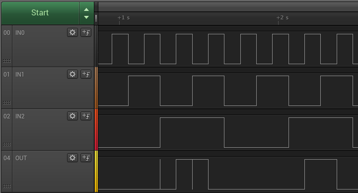
Here is an example of a LUT which sets its output according to the following equation : OUT = IN2 AND (IN0 XOR IN1). Three GPIOs are wired to the GLOC inputs to illustrate how the output is automatically driven according to these inputs, and how the filter affects the signal.
#include <carbide.h>
#include <core.h>
#include <gloc.h>
#include <gpio.h>

// Commands for the input pins
// Since the GLOC's inputs cannot be directly controlled as GPIOS,
// we need to control another set of pins and externally wire them to
// the GLOC's inputs for this example : PA09 is wired to PA06 (IN0),
// PA10 to PA04 (IN1), and PA11 to PA05 (IN2)
const GPIO::Pin IN0 = GPIO::PA09;
const GPIO::Pin IN1 = GPIO::PA10;
const GPIO::Pin IN2 = GPIO::PA11;

// Output is PA08.

// LUT number to use
const GLOC::LUT LUT = GLOC::LUT::LUT0;

int main() {
    // Initialize the board
    Carbide::init();

    // Enable the outputs that drive the GLOC's inputs (see above)
    GPIO::enableOutput(IN0, GPIO::LOW);
    GPIO::enableOutput(IN1, GPIO::LOW);
    GPIO::enableOutput(IN2, GPIO::LOW);

    // Enable the LUT with IN0, IN1 and IN2
    GLOC::enable(LUT, true, true, true);

    // Configure the LUT with a truth table equivalent to this equation :
    // OUT = IN2 AND (IN0 XOR IN1)
    // Syntax : GLOC::set(LUT, OUT, IN0, IN1, IN2)
    // Note that the output is LOW by default and only the two lines
    // setting it to HIGH are actually necessary, they are all shown here
    // only for illustration purposes
    GLOC::set(LUT, false,  false, false, false);  // 0,0,0 => 0
    GLOC::set(LUT, false,    true, false, false); // 1,0,0 => 0
    GLOC::set(LUT, false,   false,  true, false); // 0,1,0 => 0
    GLOC::set(LUT, false,   true,  true, false);  // 1,1,0 => 0
    GLOC::set(LUT, false,  false, false,  true);  // 0,0,1 => 0
    GLOC::set(LUT, true,    true, false,  true);  // 1,0,1 => 1
    GLOC::set(LUT, true,   false,  true,  true);  // 0,1,1 => 1
    GLOC::set(LUT, false,   true,  true,  true);  // 1,1,1 => 0

    bool filter = false;
    while (true) {
        // Alternate between one pass without filter and one without
        if (filter) {
            GLOC::enableFilter(LUT);
        } else {
            GLOC::disableFilter(LUT);
        }
        filter = !filter;

        // Command the inputs to test every possible combination
        GPIO::setLow(IN2);
        GPIO::setLow(IN1);
        GPIO::setLow(IN0);
        Core::sleep(100);
        GPIO::setHigh(IN0);
        Core::sleep(100);
        GPIO::setHigh(IN1);
        GPIO::setLow(IN0);
        Core::sleep(100);
        GPIO::setHigh(IN0);
        Core::sleep(100);
        GPIO::setHigh(IN2);
        GPIO::setLow(IN1);
        GPIO::setLow(IN0);
        Core::sleep(100);
        GPIO::setHigh(IN0);
        Core::sleep(100);
        GPIO::setHigh(IN1);
        GPIO::setLow(IN0);
        Core::sleep(100);
        GPIO::setHigh(IN0);
        Core::sleep(100);
    }
}
API
output for the given LUT when the inputs match the given state.truth represents the output state for each combination of inputs, with IN0 the LSB and IN3 the MSB.Enable the glitch filter for the given LUT. This filter uses the generic clock GCLK5_GLOC_TC0 mapped to the given input with the given divider. This will filter out glitches that are shorter than the divided clock period, but will also delay the output update to about 4 divided clock periods (about 300µs with the default settings).
The filter can be enabled or disabled independently on both LUTs, but if it is enabled on both, they necessarily share the same clock settings.
Set the GPIO pin used for this port. PinFunction can be IN0, IN1, IN2, IN3 or OUT.
Hacking
The GLOC module is pretty straightforward and all its functionnality are covered in this module.
Code
Header
#ifndef _GLOC_H_
#define _GLOC_H_

#include <stdint.h>
#include <scif.h>
#include "gpio.h"

// Glue Logic Controller
// This module manages truth tables to use some of the chip's pins
// as programmable logic gates
namespace GLOC {

    // Peripheral memory space base address
    const uint32_t GLOC_BASE = 0x40060000;
    const uint32_t GLOC_REG_SIZE = 0x08;
    const int N_GLOC = 2;

    // Registers addresses
    const uint32_t OFFSET_CR0 =    0x00; // Control Register 0
    const uint32_t OFFSET_TRUTH0 = 0x04; // Truth Table Register 0

    // Subregisters
    const uint32_t CR0_AEN = 0;
    const uint32_t CR0_FILTEN = 31;
    const uint32_t TRUTH0_TRUTH = 0;

    enum class LUT {
        LUT0 = 0,
        LUT1 = 1
    };

    enum class PinFunction {
        IN0,
        IN1,
        IN2,
        IN3,
        OUT
    };


    // Module functions
    void enable(LUT lut, bool in0, bool in1=false, bool in2=false, bool in3=false);
    void disable(LUT lut);
    void set(LUT lut, bool output, bool in0, bool in1=false, bool in2=false, bool in3=false);
    void setLUT(LUT lut, uint16_t truth);
    void enableFilter(LUT lut, SCIF::GCLKSource clock=SCIF::GCLKSource::RCSYS, uint16_t divider=10);
    void disableFilter(LUT lut);
    void setPin(LUT lut, PinFunction function, GPIO::Pin pin);

}


#endif
Module
#include "gloc.h"
#include "pm.h"

namespace GLOC {

    // Package-dependant, defined in pins_sam4l_XX.cpp
    extern struct GPIO::Pin PINS_IN[][4];
    extern struct GPIO::Pin PINS_OUT[];

    bool _filterEnabled[2] = {false, false};


    void enable(LUT lut, bool in0, bool in1, bool in2, bool in3) {
        // Enable the clock
        PM::enablePeripheralClock(PM::CLK_GLOC);

        // Configure inputs
        (*(volatile uint32_t*)(GLOC_BASE + static_cast<int>(lut) * GLOC_REG_SIZE + OFFSET_CR0))
            = 0 << CR0_FILTEN       // FILTEN : disable glitch filter
            | in0 << CR0_AEN        // AEN : enable inputs
            | in1 << (CR0_AEN + 1)
            | in2 << (CR0_AEN + 2)
            | in3 << (CR0_AEN + 3);

        // Set pins in peripheral mode
        if (in0) {
            GPIO::enablePeripheral(PINS_IN[static_cast<int>(lut)][0]);
        }
        if (in1) {
            GPIO::enablePeripheral(PINS_IN[static_cast<int>(lut)][1]);
        }
        if (in2) {
            GPIO::enablePeripheral(PINS_IN[static_cast<int>(lut)][2]);
        }
        if (in3) {
            GPIO::enablePeripheral(PINS_IN[static_cast<int>(lut)][3]);
        }
        GPIO::enablePeripheral(PINS_OUT[static_cast<int>(lut)]);
    }

    void disable(LUT lut) {
        // Free pins
        GPIO::disablePeripheral(PINS_IN[static_cast<int>(lut)][0]);
        GPIO::disablePeripheral(PINS_IN[static_cast<int>(lut)][1]);
        GPIO::disablePeripheral(PINS_IN[static_cast<int>(lut)][2]);
        GPIO::disablePeripheral(PINS_IN[static_cast<int>(lut)][3]);
        GPIO::disablePeripheral(PINS_OUT[static_cast<int>(lut)]);
    }

    void set(LUT lut, bool output, bool in0, bool in1, bool in2, bool in3) {
        // Compute the offset corresponding to these inputs in the LUT
        int offset = in0 | (in1 << 1) | (in2 << 2) | (in3 << 3);

        // Update the truth table
        if (output) {
            (*(volatile uint32_t*)(GLOC_BASE + static_cast<int>(lut) * GLOC_REG_SIZE + OFFSET_TRUTH0))
                |= 1 << offset;
        } else {
            (*(volatile uint32_t*)(GLOC_BASE + static_cast<int>(lut) * GLOC_REG_SIZE + OFFSET_TRUTH0))
                &= ~(uint32_t)(1 << offset);
        }
    }

    void setLUT(LUT lut, uint16_t truth) {
        // Set the truth table
        (*(volatile uint32_t*)(GLOC_BASE + static_cast<int>(lut) * GLOC_REG_SIZE + OFFSET_TRUTH0))
            = truth << TRUTH0_TRUTH;
    }

    void enableFilter(LUT lut, SCIF::GCLKSource clock, uint16_t divider) {
        _filterEnabled[static_cast<int>(lut)] = true;

        // Enable the generic clock on which the filter is based
        SCIF::enableGenericClock(SCIF::GCLKChannel::GCLK5_GLOC_TC0, clock, false, divider);

        // Enable the filter for this LUT
        (*(volatile uint32_t*)(GLOC_BASE + static_cast<int>(lut) * GLOC_REG_SIZE + OFFSET_CR0))
            |= 1 << CR0_FILTEN;
    }

    void disableFilter(LUT lut) {
        _filterEnabled[static_cast<int>(lut)] = false;

        // Disable the generic clock on which the filter is based if it is not used anymore
        if (!_filterEnabled[0] && !_filterEnabled[1]) {
            SCIF::disableGenericClock(SCIF::GCLKChannel::GCLK5_GLOC_TC0);
        }

        // Disable the filter for this LUT
        (*(volatile uint32_t*)(GLOC_BASE + static_cast<int>(lut) * GLOC_REG_SIZE + OFFSET_CR0))
            &= ~(uint32_t)(1 << CR0_FILTEN);
    }

    void setPin(LUT lut, PinFunction function, GPIO::Pin pin) {
        switch (function) {
            case PinFunction::IN0:
                PINS_IN[static_cast<int>(lut)][0] = pin;
                break;

            case PinFunction::IN1:
                PINS_IN[static_cast<int>(lut)][1] = pin;
                break;

            case PinFunction::IN2:
                PINS_IN[static_cast<int>(lut)][2] = pin;
                break;

            case PinFunction::IN3:
                PINS_IN[static_cast<int>(lut)][3] = pin;
                break;

            case PinFunction::OUT:
                PINS_OUT[static_cast<int>(lut)] = pin;
                break;
        }
    }

}