DAC module reference
#include <dac.h>Makefile :
MODULES+=dac
Description
The DAC (Digital to Analog Converter) is a peripheral that is able to output an analog voltage on a pin. This can be useful for an arbitrary waveform generator (AWG), to control the amplification of a transistor, ...
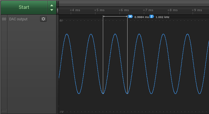
If you want to generate an arbitrary waveform, the DMA can be used to feed the DAC with the content of a buffer. For this, define an array of size n, fill it with the samples for one period of the signal you want to generate, and use setFrequency() to specify at which frequency the samples need to be sent (this is the frequency of your signal multiplied by the number of samples in each period). You can then use start(), isReloadEmpty() and reload() to start the conversion. In order to continuously repeat the buffer, simply set the repeat flag to true when calling start(). For example, a sinewave can be generated with the following code :
#include <carbide.h>
#include <core.h>
#include <dac.h>

// Precomputed sinewave with 128 samples
// Generated with the following Python snippet :
// [int(511 * math.sin(2*math.pi*x/128) + 512) for x in range(0,128)]
uint16_t sin[] = {512, 537, 562, 586, 611, 636, 660, 684, 707, 730,
    752, 774, 795, 816, 836, 855, 873, 890, 907, 922, 936, 950, 962,
    973, 984, 993, 1000, 1007, 1013, 1017, 1020, 1022, 1023, 1022,
    1020, 1017, 1013, 1007, 1000, 993, 984, 973, 962, 950, 936, 922,
    907, 890, 873, 855, 836, 816, 795, 774, 752, 730, 707, 684, 660,
    636, 611, 586, 562, 537, 512, 486, 461, 437, 412, 387, 363, 339,
    316, 293, 271, 249, 228, 207, 187, 168, 150, 133, 116, 101, 87,
    73, 61, 50, 39, 30, 23, 16, 10, 6, 3, 1, 1, 1, 3, 6, 10, 16, 23,
    30, 39, 50, 61, 73, 87, 101, 116, 133, 150, 168, 187, 207, 228,
    249, 271, 293, 316, 339, 363, 387, 412, 437, 461, 486};
const int N = sizeof(sin) / 2; // Divided by two because each sample
                               // is two-byte long

int main() {
    // Initialize the board
    Carbide::init();

    // Enable the DAC
    DAC::enable();

    // Set the sample frequency of the DAC to output a 1kHz sinewave
    DAC::setFrequency(1000 * N);

    // Start the DAC with the repeat flag enabled
    DAC::start(sin, N, true);

    while (true) {
        // ...
    }
}
There are two other peripherals that can be used for similar purposes :
- The ADAC (Audio DAC) is a peripheral dedicated to output sound. It features a two-channel DAC (for stereo) with specialized hardware and a bandwith tuned for the human ear. However, this module is not currently implemented.
- The TC (Timers/Counters) can be configured to output PWM signals, i.e. a square wave signal with a fixed frequency and a modulated duty cycle. When coupled with an external filtering capacitor or used to control a device that is not sensitive to high frequency changes (such as an LED or a DC motor), a PWM signal looks a lot like the output of a DAC.
Note : the DAC output is always referenced to the Vref pin (next to the Vcc pin on Carbide) : the output voltage varies linearly between 0V (value=0) and Vref (value=1023). Remember to provide a voltage on Vref in order to see an output on the DAC.
API
write() or start().value must be between 0 and 1023.buffer of length n. The DAC will use the DMA to output each of the samples in the buffer in order and at the frequency specified using setFrequency(). If repeat is set to true, the same samples will be repeated indefinitely, otherwise the DAC will stop at the last sample in the buffer (and keep the current value).start()) is finished.start() is called. Return true if the given frequency is within bounds.true if the current operation started with start() is finished.true if the DAC is ready to receive a new buffer with reload().interrupt=Interrupt::TRANSFER_FINISHED) or when the DAC is ready to receive a new buffer with reload() (interrupt=Interrupt::RELOAD_EMPTY).Hacking
The DAC peripheral is pretty straightforward and doesn't allow much customization.
Code
Header
#ifndef _DAC_H_
#define _DAC_H_

#include <stdint.h>
#include "gpio.h"

// Digital to Analog Converter
// This module is used to generate an analog voltage on a pin
namespace DAC {

    // Peripheral memory space base address
    const uint32_t DAC_BASE = 0x4003C000;

    // Registers addresses
    const uint32_t OFFSET_CR =      0x00; // Control Register
    const uint32_t OFFSET_MR =      0x04; // Mode Register
    const uint32_t OFFSET_CDR =     0x08; // Conversion Data Register
    const uint32_t OFFSET_IER =     0x0C; // Interrupt Enable Register
    const uint32_t OFFSET_IDR =     0x10; // Interrupt Disable Register
    const uint32_t OFFSET_IMR =     0x14; // Interrupt Mask Register
    const uint32_t OFFSET_ISR =     0x18; // Interrupt Status Register
    const uint32_t OFFSET_WPMR =    0xE4; // Write Protect Mode Register
    const uint32_t OFFSET_WPSR =    0xE8; // Write Protect Status Register

    // Constants
    const uint32_t CR_SWRST = 0;
    const uint32_t MR_TRGEN = 0;
    const uint32_t MR_TRGSEL = 1;
    const uint32_t MR_DACEN = 4;
    const uint32_t MR_WORD = 5;
    const uint32_t MR_STARTUP = 8;
    const uint32_t MR_CLKDIV = 16;
    const uint32_t WPMR_WPEN = 0;
    const uint32_t WPMR_WPKEY = 0x444143 << 8;

    enum class Interrupt {
        RELOAD_EMPTY,
        TRANSFER_FINISHED
    };


    // Module API
    void enable();
    void disable();
    void write(uint16_t value); // 0 <= value <= 1023
    void start(uint16_t* buffer, int n, bool repeat=false);
    void reload(uint16_t* buffer, int n);
    void stop();
    bool setFrequency(unsigned long frequency);
    bool isFinished();
    bool isReloadEmpty();
    void enableInterrupt(void (*handler)(), Interrupt interrupt=Interrupt::TRANSFER_FINISHED);
    void disableInterrupt(Interrupt interrupt=Interrupt::TRANSFER_FINISHED);
    void setPin(GPIO::Pin pin);

}


#endif
Module
#include "dac.h"
#include "pm.h"
#include "dma.h"

namespace DAC {

    // Package-dependant, defined in pins_sam4l_XX.cpp
    extern struct GPIO::Pin PIN_VOUT;

    bool _enabled = false;
    int _dmaChannel = -1;

    // Enable the DAC controller
    void enable() {
        // Enable the clock
        PM::enablePeripheralClock(PM::CLK_DAC);

        // Set the pin in peripheral mode
        GPIO::enablePeripheral(PIN_VOUT);

        // CR (Control Register) : issue a software reset
        (*(volatile uint32_t*)(DAC_BASE + OFFSET_CR))
            = 1 << CR_SWRST;

        // WPMR (Write Protect Mode Register) : unlock the MR register
        (*(volatile uint32_t*)(DAC_BASE + OFFSET_WPMR))
            = WPMR_WPKEY
            | 0 << WPMR_WPEN;

        // MR (Mode Register) : setup and enable the DAC
        (*(volatile uint32_t*)(DAC_BASE + OFFSET_MR))
            = 0 << MR_TRGEN         // TRGEN : internal trigger
            | 1 << MR_DACEN         // DACEN : enable DAC
            | 0 << MR_WORD          // WORD : half-word transfer
            | 100 << MR_STARTUP     // STARTUP : startup time ~12µs
            | 0 << MR_CLKDIV;    // CLKDIV : clock divider for internal trigger

        // WPMR (Write Protect Mode Register) : lock the MR register
        (*(volatile uint32_t*)(DAC_BASE + OFFSET_WPMR))
            = WPMR_WPKEY
            | 1 << WPMR_WPEN;

        _dmaChannel = DMA::setupChannel(_dmaChannel, DMA::Device::DAC, DMA::Size::HALFWORD);

        _enabled = true;
    }

    // Disable the DAC controller and free ressources
    void disable() {
        // WPMR (Write Protect Mode Register) : unlock the MR register
        (*(volatile uint32_t*)(DAC_BASE + OFFSET_WPMR))
            = WPMR_WPKEY
            | 0 << WPMR_WPEN;

        // MR (Mode Register) : disable the DAC
        (*(volatile uint32_t*)(DAC_BASE + OFFSET_MR)) = 0;

        // Free the pin
        GPIO::disablePeripheral(PIN_VOUT);

        // Disable the clock
        PM::disablePeripheralClock(PM::CLK_DAC);
    }

    void write(uint16_t value) {
        // Enable the DAC controller if it is not already
        if (!_enabled) {
            enable();
        }

        // Cut high values
        if (value > 1023) {
            value = 1023;
        }

        // CDR (Conversion Data Register) : write new value
        (*(volatile uint32_t*)(DAC_BASE + OFFSET_CDR)) = value;
    }

    void start(uint16_t* buffer, int n, bool repeat) {
        // Enable the DAC controller if it is not already
        if (!_enabled) {
            enable();
        }

        // Stop any previous operation
        DMA::stopChannel(_dmaChannel);

        if (!repeat) {
            // Disable the ring mode of the DMA channel
            DMA::disableRing(_dmaChannel);

            // Start a new operation
            DMA::startChannel(_dmaChannel, (uint32_t)buffer, n);

        } else {
            // Enable the ring mode of the DMA channel
            DMA::enableRing(_dmaChannel);

            // Start a new operation
            DMA::startChannel(_dmaChannel, (uint32_t)buffer, n);

            // Reload the DMA channel with the same buffer, which
            // will be repeated indefinitely
            DMA::reloadChannel(_dmaChannel, (uint32_t)buffer, n);
        }
    }

    void reload(uint16_t* buffer, int n) {
        // Enable the DAC controller if it is not already
        if (!_enabled) {
            enable();
        }

        // Reload the DMA
        DMA::reloadChannel(_dmaChannel, (uint32_t)buffer, n);
    }

    void stop() {
        // Enable the DAC controller if it is not already
        if (!_enabled) {
            enable();
        }

        // Stop the DMA
        DMA::stopChannel(_dmaChannel);
    }

    bool isFinished() {
        // Enable the DAC controller if it is not already
        if (!_enabled) {
            enable();
        }

        return DMA::isFinished(_dmaChannel);
    }

    bool isReloadEmpty() {
        // Enable the DAC controller if it is not already
        if (!_enabled) {
            enable();
        }

        return DMA::isReloadEmpty(_dmaChannel);
    }

    bool setFrequency(unsigned long frequency) {
        // Enable the DAC controller if it is not already
        if (!_enabled) {
            enable();
        }

        // Compute the clock divider for the internal trigger
        if (frequency == 0) {
            return false;
        }
        unsigned long clkdiv = PM::getModuleClockFrequency(PM::CLK_DAC) / frequency;
        if (clkdiv > 0xFFFF) {
            return false;
        }

        // WPMR (Write Protect Mode Register) : unlock the MR register
        (*(volatile uint32_t*)(DAC_BASE + OFFSET_WPMR))
            = WPMR_WPKEY
            | 0 << WPMR_WPEN;

        // MR (Mode Register) : update CLKDIV
        uint32_t mr = (*(volatile uint32_t*)(DAC_BASE + OFFSET_MR));
        (*(volatile uint32_t*)(DAC_BASE + OFFSET_MR))
            = (mr & 0x0000FFFF)
            | clkdiv << MR_CLKDIV;

        // WPMR (Write Protect Mode Register) : lock the MR register
        (*(volatile uint32_t*)(DAC_BASE + OFFSET_WPMR))
            = WPMR_WPKEY
            | 1 << WPMR_WPEN;

        return true;
    }

    void enableInterrupt(void (*handler)(), Interrupt interrupt) {
        // Enable the DAC controller if it is not already
        if (!_enabled) {
            enable();
        }

        // Enable the interrupt directly in the DMA
        DMA::enableInterrupt(_dmaChannel, handler, static_cast<DMA::Interrupt>(interrupt));
    }

    void disableInterrupt(Interrupt interrupt) {
        // Enable the DAC controller if it is not already
        if (!_enabled) {
            enable();
        }

        // Disable the interrupt in the DMA
        DMA::disableInterrupt(_dmaChannel, static_cast<DMA::Interrupt>(interrupt));
    }

    void setPin(GPIO::Pin pin) {
        PIN_VOUT = pin;
    }

}